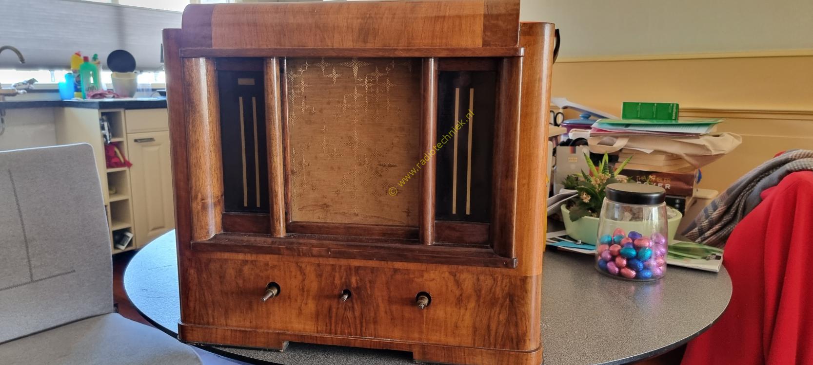
It was the height of summer when this beautiful temple of music became my property. The buttons were loose in the cabinet, except for the AL2 power tube, almost complete.

The cabinet is in beautiful condition. The speaker cloth is original but torn. Unfortunately the scales are no longer legible.

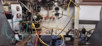
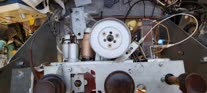
The inside is a bit shocking. The device has already been restored. The wiring has been renewed and the electrolytic capacitors have been replaced by defective ones from the 1950s/60s. And then it is also the 25Hz version.

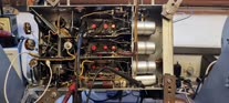
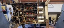
The underside has also been restored. The beautiful yellow capacitors immediately remind you of the 1960s. Here too, parts of the wiring have already been replaced. And yet I am very happy with the device. And we will restore the device to the original.

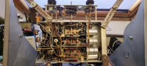
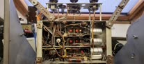
A chassis of a Philips 535A really in new condition but unfortunately demolished. This chassis is ideal for use with the Philips 536A. There are only a few detail differences.

This is the chassis from the Philips 536A. We will use this to build the other chassis. Of course we only use original parts.

We will use the top plate of the Philips 536A to drill the missing holes in the Philips 535A chassis. Consider attaching the front plate but also the holes for the extra trimmers.

And here the top plate of the Philips 536A on top of the Philips 535A. Now you can see which holes are missing and need to be made.

And here the first holes are drilled in the Philips 535A chassis. We will drill out the holes for the trimmers with a Christmas tree drill.

First let's measure how we are doing. This is absolutely in the right place.

The holes are drilled out with the Christmas tree drill. And the rest of the holes have now also been drilled.

Because the Philips 535A chassis is completely different from the Philips 536A, we will start by removing the high-frequency part.

And here the complete high-frequency part slides out of the chassis.

This gives space now I can deburr my newly drilled holes. The order in which components are placed is very important. The structure of the Philips 536A chassis is quite complex and you need to be able to reach everything with the soldering iron.
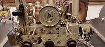
Because the music temple has two enormous tuning towers, the drive has been reinforced. This is done by means of a tension spring. Here's how the whole thing works.

The wave range switches are cleaned according to an old recipe. So no contact spray!

The other side is the same story.

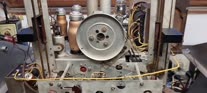
This already provides a good basis for further restoration. The Philips 535A chassis has been converted into a Philips 536A. And this chassis is in beautiful condition.

Also from the top it looks like an original Philips 536A chassis.

This is the high frequency part of the Philips 536A. Because the coils have different part numbers than those of the Philips 535A, I decided to use the original coils. But the sub chassis on which the coils are mounted is from the Philips 535A in better condition, so we will use that sub chassis.

Of course we only use original parts. We are talking about the restoration of a Philips 536A.

This is the sub chassis of the 535A. All coil cans have been removed so that the construction of the high-frequency part of the Philips 536A can begin.

And here the reconstruction of the Philips 536A high-frequency part. This gives me the feeling of the 1930s.

The sub chassis is now fully wired and the coil cans are back on. And the yellow capacitors are now black with the correct shape. This can be mounted on the chassis in one go. More components is simply not possible.

This is a Philips electrolytic capacitor. There is of course no point in measuring. They are simply defective.

With some steam you can easily remove the wrapper from the condenser. The rest can be guessed, I hope. There is no need to destroy the hoods.

And after this procedure it looks like this. An original electrolytic capacitor surrounded by a few tar capacitors and a resistor.

The IF of the Philips 536A has variable bandwidth control. Here the coil bus has been replaced with the coil bus of the Philips 536A chassis with variable bandwidth control. The 50Hz transformer has also been placed on the chassis.

The structure of the high-frequency mixer stage and oscillator. Here too, only original components were used.

This type of tar capacitor model was only used by Philips in the year 1935.

This is the circuit with the coupling capacitor between the pre and power amplifier. Even though a lot of components have been replaced, a lot of detail regarding the placement of components can still be found.

And here mounted in the new chassis. This already gives an idea of the placement of the components. There have been some changes to the Philips 536A where the high frequency filter on the diagram between the pre-amplifier and the power amplifier has been omitted. The new structure is as shown here.

The next modification is the connection of the top cap of the ABC1 tube. An extra resistor has been placed here, causing a small change in the placement of the components that directly relate to it.

The service message shows the modification. The placement of the components was no longer applicable for a long time due to the omission of the high-frequency filter between the pre and power amplifier.

This is the diagram after all changes to the device.

And this is how the modification is done in the Philips 536A chassis. And of course we will put this back again soon.

This is the original potentiometer. These are almost always replaced because they are always defective. There is a metal protective cover over the mains switch.

And this is the mains switch. the cover plate of the potentiometer has a raised edge. This was done to be able to operate the mains switch.

Because there are no drawings of the installation parts of the new situation, we will measure things. Here we use old parts of the circuits from which a lot of detail can still be extracted.

Because the detector is housed in the ABC1 tube, it is necessary to build up the IF. There are many connections to the IF that you cannot reach later.

Here the second IF coil bus has been replaced. This one was also completely different.

A small modification in the placement of the components. The tar capacitor on the potentiometer is now attached to the top of the potentiometer. The bottom of the tar capacitor is connected by a resistor at the top cap of the ABC1.

Sliding components makes it possible to place everything neatly.

And here the new component arrangement already comes into focus.

The structure of the IF goes according to plan here and the placement of the resistors.

And here a handful of tar capacitors placed in the IF.

I received these capacitors in the condition that the right capacitor is in. The previous owner thought he could break this open using hose clamps. The damage that has occurred cannot be repaired. In the automotive industry, this type of panel damage is replaced. Too bad these capacitors are not available for the taking. And it is simply possible to restore these capacitors invisibly.

There appears to be nothing wrong with the wiring of the voltage carousel.

The structure of the IF part is as you can see here. And gives a good idea of how the radio was built in the factory in 1935.

The IF is ready and the septum has been definitively placed.

Now the last measurements with the volume potentiometer.

The wiring mounted for the on and off switch and the volume potentiometer can be mounted completely with wiring in the chassis.

The potentiometer is mounted. Now we can start rebuilding the mains power supply.

Volume potentiometer axis installed, it is of course important that this axis does not connect with components anywhere.

The mains switch has been connected and the power supply has been installed, time to test some things.

And here are the first images of a working IF amplifier. it's just a start but it's going in the right direction.

The measuring transmitter is set to the IF frequency approximately. Everything still needs to be adjusted.

The underside of the chassis during the first test.

The top of the chassis during the first test. Because the transducer is still missing, the ground contact of the transformer is connected to ground via a Chinese cable.

The construction of the preamplifier and detector can now begin. The missing small electrolytic capacitors have been found.

The AVR line runs just close to the bottom of the tube base. It's starting to get quite full with components.

The detector and preamplifier are now ready. Time for a test.

And here is the image of the detector.

And here the low frequency from the preamplifier. It's still a bit rustling, but it's starting to work.

The measuring setup.

The construction of the power amplifier.

An upside-down photo of the power supply section shows no damage from leaking electrolytic capacitors.

The low frequency part is ready on a piece of AVR. Time to do some testing with a speaker.
This is AM modulated mid frequency in and speaker out.

Add the last components for the AVR line and the whole thing is ready.

Shielding plate against it. And the section is complete. Note the ground connection of the 0.5 uF capacitor located on the outside of the section.

And then it's time to place the high-frequency part. Now you will understand why that is only now possible.

What a mess but wow it's starting to look a lot like a Philips 536A now.

The front is also starting to look like something. On the right the trimmers for the newly drilled holes.

All trimmers and chassis plate are screwed down to give a better picture.

A partition with wave range switch has been installed.

The stuff is screwed down and connected.

Well, what else can you say, everything is there and it looks like it's 1935. That's what I was trying to achieve. But would the chassis also be able to play.

And then the nightmare of this radio. The connection of the top cap of the high frequency amplifier tube the AF3. Loose pieces of paper and components that do not fit and should not make a closure.

We succeeded, the stuff is in the hood over it and hm.... forgot to take a photo before the hood went on. I won't take the hood off anymore pfff.

We start by connecting things at the bottom.

What we are still missing are the power supplies for the high-frequency part. Part of it is on the trasductor transformer.

We also need some tar capacitors for the power supply.

The transducer transformer is screwed to the chassis on the left.

These are some leftovers I received. I need the electrolytic capacitor and we are going to restore it.

This is the way to restore these capacitors. The contents are completely dried up and completely decayed. That is why you don't have to think about anything else.

The power supply part on the transducer transformer.

The power supply part on the transducer transformer is ready. The other power supply for the high-frequency tuning oscillator was just put together. Time to test.

And here the first sign of life. The tuning oscillator in short wave mode.
The measuring transmitter somewhere in the short wave and...
Wave range switch shaft mounted thing tuned to the medium wave and....

After roughly tuning the oscillator, the high-frequency synchronization of the medium wave has improved enormously.
And then the radio tuned to radio monique sounds like this. Please note that the Philips window antenna is used here because the many solar panels and heat pumps cause a lot of interference.

The installation of the pick-up switch and the extra dull sound switch.

The wiring is connected to everything.
Everything still seems to work, even after the last major renovation.

Then the left side can also be added. Both trimmers are now fixed in the side and the chassis is quite complete at the bottom.
Let's do a test to see if the side doesn't touch anything so that it closes somewhere.

And then it's time for the tuning towers, the left one is on it.

The mounting of the left tuning tower was very difficult because of the transducer.

And then the question arises which font are we going to use.

Ok it will be the top font. And immediately put the tuning ribbon around the capacitor wheel.

The last hose clamp capacitor is placed. Time for the right tuning tower.
But first an idea of the chassis and structure.

The right tuning tower mounts the ribbon around the capacitor wheel and mechanically it is ready.

And then it's time for the wiring harness. The first wire has been laid. No more Chinese cords needed.
Just a little test in between. the chassis plays completely without Chinese cables. Sat is also something unique.
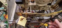
Here is the operation of the transducer transformer. When the radio is tuned correctly, the light will burn at its brightest.

Because we are heading towards Christmas, it is useful that the Christmas lights work.

It also works without a Chinese cord.

All the wires are there.

And this is the first knot.

And this is already a lot of knots.

Finished
And everything seems to be working, just take a look.

Waiting for the correct indicator lights.

The correct indicator lights are installed.

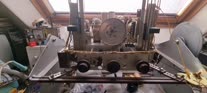
And the chassis looks like this.
Everything is original but there is one thing I don't like. But more about this later.

The chassis has been restored and plays the stars from heaven.
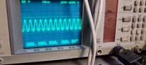
To adjust a mid frequency you need a wobulator. The signal from the wobulator is a sine wave in FM modulated with a start and a stop frequency. It looks like this.
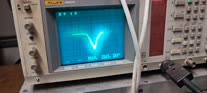
The IF of the Philips 536A has a variable adjustable bandpass filter. That makes adjustment a bit more complex. The point is that the bandpass of the IF remains linear while controlling the bandpass filter. Just look at the result.
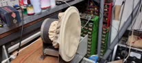
A test of the loudspeaker. It appears that with low tones the cone of the speaker rattles. And so it seems that the cone needs to be replaced. There is also a strange twist in the cone.

And now the last modification to the chassis. I ordered twine that is used for tying wire trees. It is a somewhat greasy thread and it gives even more originality.

The chassis is now ready. The cabinet is in excellent condition. But what I'm still looking for are the dials. In addition, the speaker still needs to be repaired.